The Datsun 320 front suspension is a very simple torsion bar system with Telescopic shock absorbers. Sadly it uses a combination of kingpins and threaded pivots rather than ball joints which wear out very quickly if not regularly greased.
One of the biggest traps is not noting the very subtle differences between left and right hand suspension components when dismantling and reassembling the front end.

Stub Axle Knuckle
The stub axle knuckle assemblies are different for left and right sides of the car.
The parts manual shows the following part numbers:
- 40014-07250 Right hand side
- 40015-07250 Left hand side
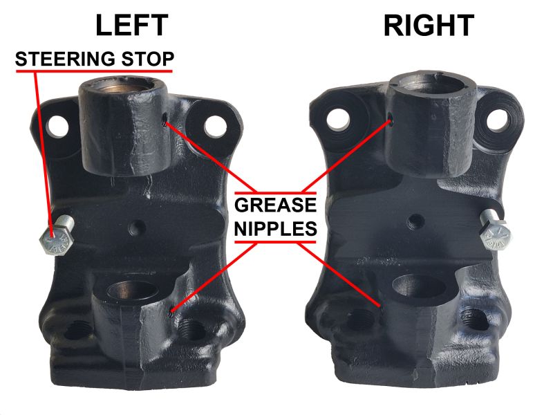
If your lucky they may have been stamped as L and R but this isn't always the case. The simple rule is the grease nipples go to the front and the steering stop adjuster goes to the back.
The parts manual diagram above shows a right side assembly 40014-0725
The photograph shows the left and right assemblies, note the opposing positions of the steering stops and the grease nipple locations.
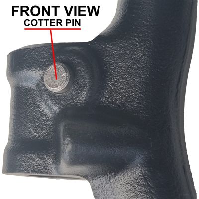
The cotter pin that locks the kingpin into the front upright support is inserted from the same side as the grease nipples. The parts manual does show the cotter pin in the opposite direction.
Front Upright Support
The front upright supports are also different for the left and right sides of the car.
The parts manual shows the following part numbers:
- 54710-08700 Right hand side
- 54711-08700 Left hand side
Annoyingly both left and right units often have the same casting number 5471004301 which is similar to a part number.
Whilst both sides may have started off life as the same casting they were machined differently.
The easiest way to identify which is left or right is the direction of the cotter pin that locks the king pin in place is inserted. The cotter pin goes in form the front of the car and nut and spring washer face the rear of the car. One side of the cotter pin hole is machined flat to accept the nut and spring washer. This flat surface should face the rear of the car.
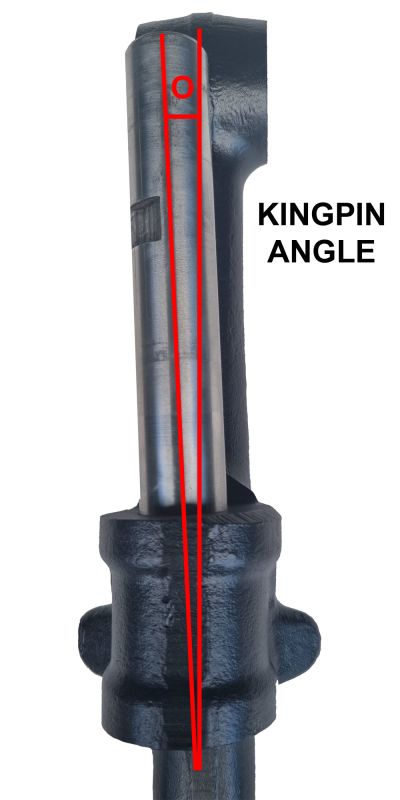
The other way is to look at the kingpin inclination. Its not easy to see unless to insert the king pin then you can see the top of the kingpin should tilt towards the back of the car and the bottom should tilt towards the front of the car.
Steering Arm Knuckle
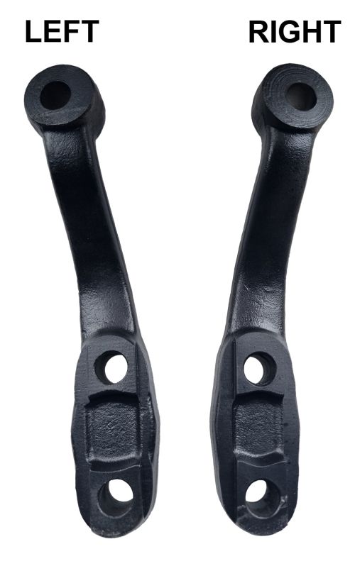
The steering arm knuckle assemblies are also different for left and right sides of the car.
The parts manual shows the following part numbers:
- 40052-08700 Right hand side
- 40053-08700 Left hand side
Some of the steering arm knuckles have the part number cast into them but thats not always the case.
The arms have a bend in them and they should be installed with the bend towards the outside so that the steering arm ball joint is closest to the inside of the road wheel.
It they are inserted the wrong way around there is insufficient adjustment in the steering arms to correct the wheel alignment and the steering Ackerman angles will also be incorrect.
Note: Ackerman angle is what makes the inner and outer wheels turn through a different arcs when turning.
King Pin
The King Pin assembly for each side is identical and is made up from the following parts
- 2 x 40030-25660 Welsh Plugs
- 1 x 40022-25660 King Pin
- 1 x 40031-26760 thrust bearing
- 40032-25660 - shim .075 (as required)
- 40033-25660 - shim .250 (as required)
- 40034-25560 - shim .750 (as required)
- 2 x 40016-26762 Bushes
- 1 x 40023-25660 Cotter Pin plus nut and washer
When installing the king pin assembly the thrust bearing should be placed at the bottom the front upright support with the bearing cup facing down. The shims should be placed at the top of the front upright support. Never put the shims at the bottom as they will not handle the load and will be destroyed by the loads placed upon them.
Before inserting the bushes ensure the inner surface of the stub axle knuckle is clean and there are no scratches. A light hone of the with some medium grade wet and dry sand paper is advised.
It is best to get a machine shop to install the bushes. If the king pin does not rotate freely then the bushes may need to be reamed to size.
Use the "as required" shims to eliminate all end float.
Completed Assembly
The image here shows the complete right side assembly of the follwing items
- Stub Axle Knuckle
- Front Ubright Support
- King Pin
- Steering Arm Knuckle
Note the orientation of the Grease nipples, Steering lock bolt (hidden from view), Cotter pin and Steering arm knuckle.


